If you’ve ever tried to project slab boundaries onto a topography in Revit, you already know how deceptively time-consuming it can be. Drawing floors that follow the ground slope “just right” often turns into hours of manual adjustments.
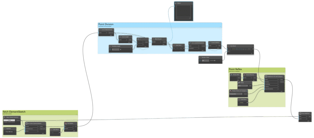
This post walks through a Dynamo workflow that automates the whole process extracting slab boundaries, generating projection points, bouncing them onto the topography and finally recreating floors that follow the terrain. The approach is based on an excellent tutorial by AussieBIMGuru (huge thanks!) and simplified wherever possible.
You will need two free Dynamo packages: SpringNodes and Data-Shapes.
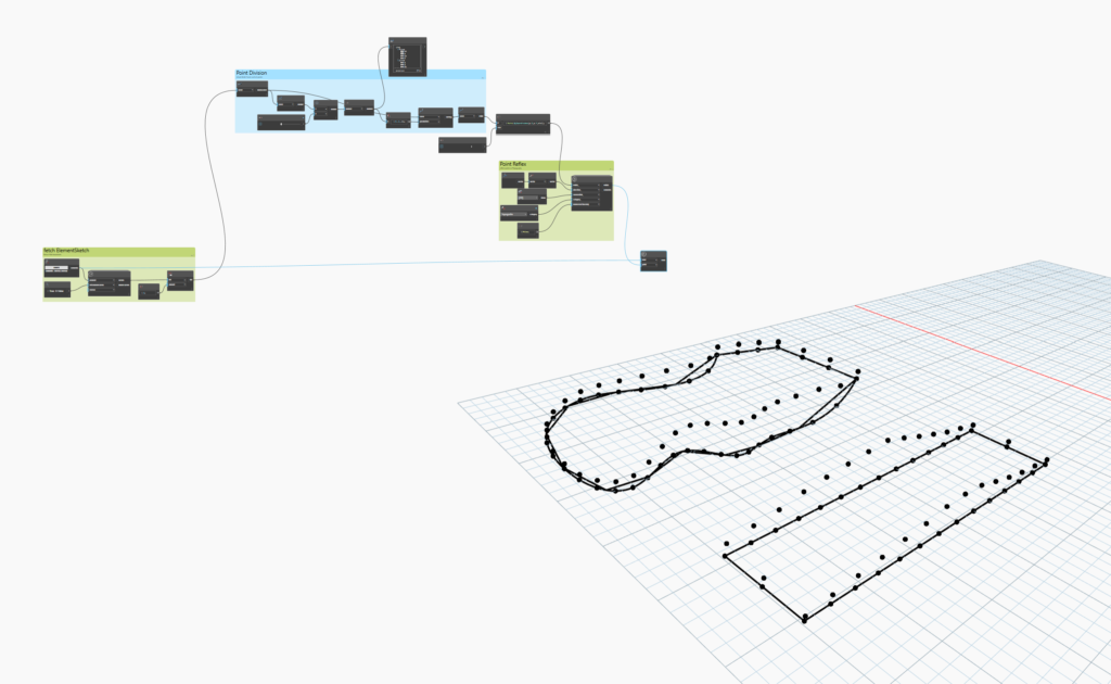
1. Extracting the Original Slab Boundaries
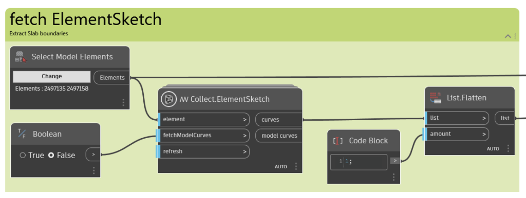
We start by gathering all the slab or floor elements you want to project onto the topography. Once selected, the goal is to retrieve their boundary curves.
The Collect.ElementSketch node from SpringNodes does exactly this. Feed your slabs into the node and flatten the resulting list, this ensures all boundaries sit in one clean and linear collection of curves.
2. Dividing the Curves into Points
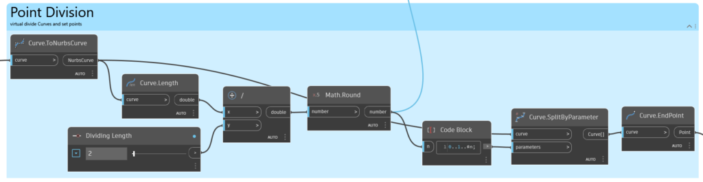
With the boundaries extracted, the next step is to create a set of points that represent each curve’s shape. These points will later be projected onto the topography.
Convert all boundary curves to nurbs curves
This standardizes the geometry, resulting in a clean list of elements of the same type.
Determine the number of divisions
Take the curve length and divide it by your desired point spacing (the “division length” parameter). Then round the result using Math.Round.
Shorter spacing = more points = higher accuracy.
Divide the curves
Use the division count to generate the actual points.
After that, extract the endpoints of each divided segment, which will form the basis of our projection onto the terrain.
3. Projecting Points onto the Topography
Once the points are ready, we need to “drop” them onto the topography surface.
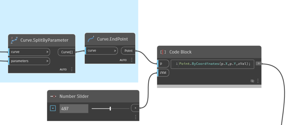
Elevate the points first
To guarantee a successful projection, raise all points along the Z-axis to a safe height—high enough that every point will definitely intersect the terrain when projected downward.
Technically, you can skip this if you always know the correct direction, but raising the points makes the workflow universal and far more reliable.
Use the “RayBounce On Link Category” node
From Data-Shapes, this node allows you to shoot rays from the elevated points down (or up) toward the topography.
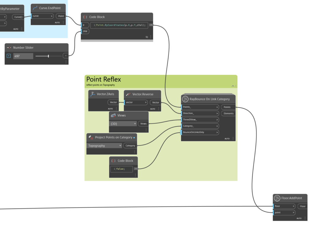
Connect the following:
- The elevated points
- A reversed vector, pointing from the raised points down toward the terrain
- A 3D view
- The topography category
- Your preferred BounceOnLinksOnly setting, depending on whether your topo lives in a linked model
This node returns the reflected points, the points actually sitting on the topography.
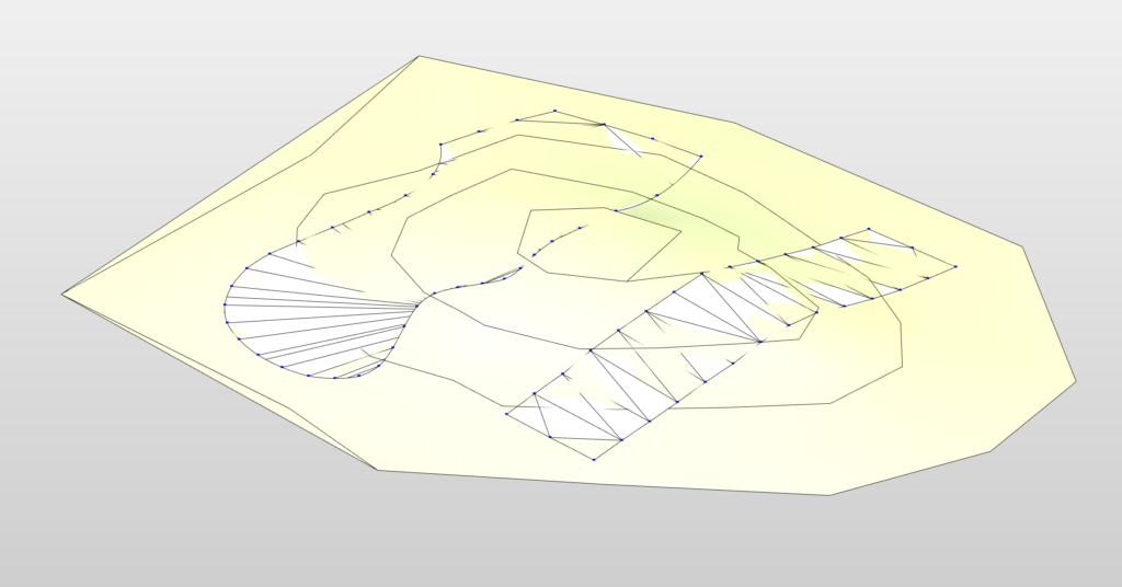
4. Creating the New Floors
With the reflected points ready, it’s time for the payoff.
Use Floor.AddPoint (a native Dynamo node) and connect:
- The reflected points (the projected geometry)
- The original slab elements you selected at the beginning
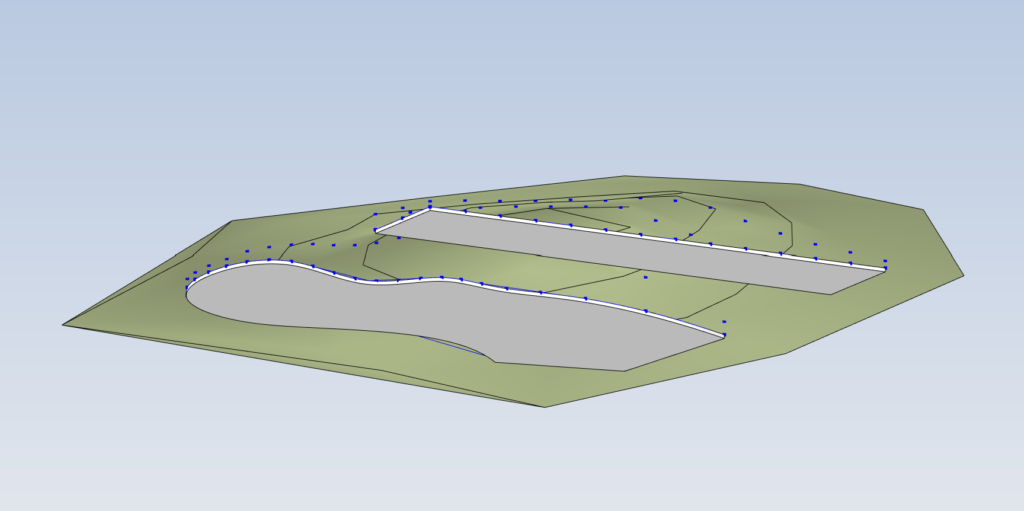
Dynamo will generate new floors that follow the exact contour of the topography using the updated point positions.
And that’s it, your slabs now automatically adapt to the terrain without having to play with them for hours.
Short in time or feeling lazy? Get it ready from Google Drive!